As with any custom project, it comes with much Challenges and Triumphs.
Join us on our journey as we dive into the intricate process of designing and assembling the ‘Brain Board’—a custom RP2040-based control board—for our innovative toy car project. In this post, we’ll explore the hurdles we’ve encountered with power delivery issues and our strategies to troubleshoot and overcome them. Get an inside look at our PCB club’s collaborative efforts and the valuable learning experiences we’ve gained.
Introduction
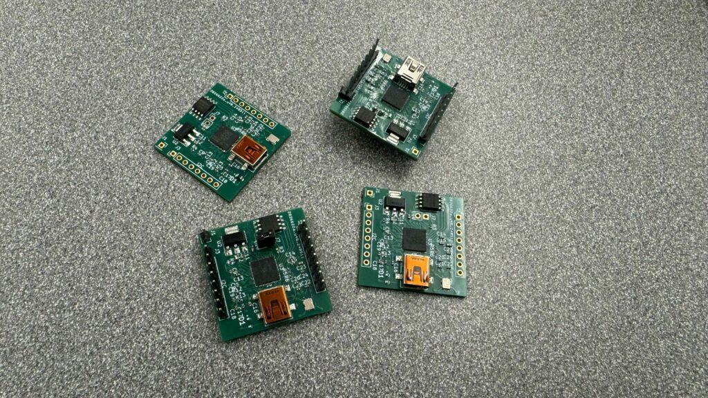
This custom PCB board is a 1.25 by 1.25 inch 6 layer board, which is even smaller than the orginal Raspberry Pi Pico. The board is based on the custom standard I made, which have a pair of 8 pin connectors. It is used to standardize all of the sensor board, power distrubution board, and motor controller.
The whole project is a PCB Club project, which is a student led (me), event within a makerspace. We meet up once a week, and we bond together to design board and stuff.
With the convience, it also come with challenges. The board is too small! The small size required smaller part, and this is my first time using 0402 part, which my clubmates told me it is very hard to put it on and reflow it properly. Oh well, I guess I could choose something like 0603, but that should not prevent it from working.
What’s the issue
Well, after we built 4 board, I finally sit down and debug it, as it should not be a soldering issue, instead could be a design issue.
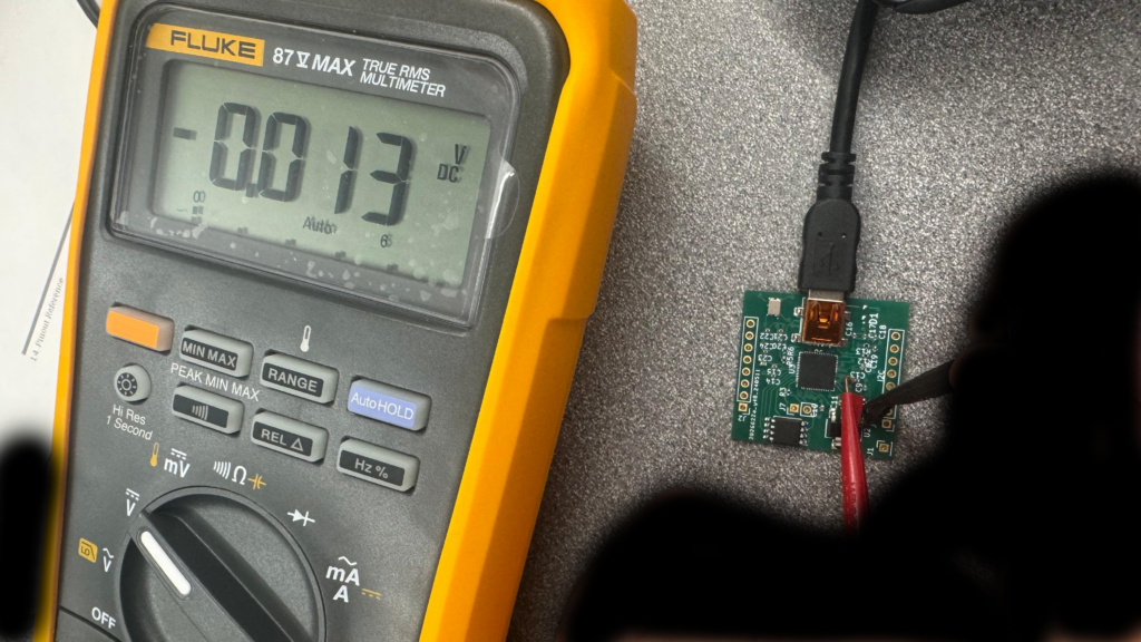
In the image, I am meausring the C13 Capicitor, which is linked to the 1.1V core supply for RP2040, and you know what a got, a flat 0! A 0. Which means something is really wrong.
I don’t know what is the issue yet, but our clubmates is soldering more of them, using some older RP2040 we get, perhaps the batch we get have issue, as I am using a proof to be work schematic from older project. We will see how to goes, and keep your guys updated.